USB Connector Technology: A Deep Dive into Architecture, Pinouts, and Signaling
The extensive use of USB connector technology across thousands of consumer, commercial, industrial, and military products and systems is due to three proven assets: economy, efficiency, and simplicity. USB solutions have proven to be cost-effective compared to other interconnects. They can handle both data and power in the same connector. And their design is elegant and robust, with simple user insertion and removal. Let’s take some time to dive into USB technology. Shop Same Sky’s full range of USB connectors and USB cables.
A Quick Look Back
Released early in 1996, the USB (Universal Serial Bus) standard was an attempt to simplify the confusing array of connectors being used to transfer data and power between computers and peripherals, limiting their interconnectivity and interoperability. The USB Implementers Forum (USB-IF) issued the initial USB standard in 1996. Since then, over 14 different versions have been released, with each iteration offering connector design specs that improved both data transfer speed and power handling capacity.
If you’d like to dig deeper into the development history of the USB protocol, go to the Same Sky blog, The History of USB Standards from 1.0 to USB4. Interested in more USB connectors content? Check out our other blog topics:
- How USB Connectors Enable Modern IoT, Industrial, Medical, and More
- Getting Started with USB: Integrating a USB Connector into Your Product
- What You Need to Know About USB Connectors and USB Cables
- USB Type C and USB 3.2 – Clarifying the Connection
- An Introduction to Power-Only USB Type C Connectors
- Or watch our USB connectors and standards video
Anatomy and Configuration of USB Connectors
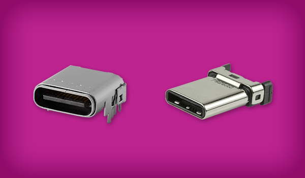
All USB connectors have several things in common. They have at least four internal contacts or pins. Newer versions have more pins depending on their type, with USB-C housing 24 pins. These contacts are used for power, data, and ground. In use, the power pins always make a connection before the data lines to avoid power flowing over the data lines. USB interconnects are also directed, meaning that only “downstream” facing pins provide power that connects to the “upstream” ports of devices. This prevents electrical overload and damage to equipment. The metal shell of the connector also connects with the peripheral device prior to any pin interconnect, effectively protecting the pins from damage during insertion.
USB Host and Peripheral Architecture
In order to efficiently manage communication, standard USB technology employs a host/device architecture. The USB standard spells out a difference between host and peripheral devices, and the connectors reflect this. In a USB interconnect, the host is the controlling device that communicates with and powers other devices. A peripheral is a device that connects to the host.
A host (like a computer) controls the data flow on the USB bus. A peripheral (like a hard drive) receives instructions from the host and only sends data when requested. Some devices may act as both a host and peripheral (smartphones), which allows them to connect to other peripherals or to connect to a computer. In general, if implementing standard USB protocol, a device must assume either a host role or a peripheral role.
USB Connector Pinouts and Wiring Functions
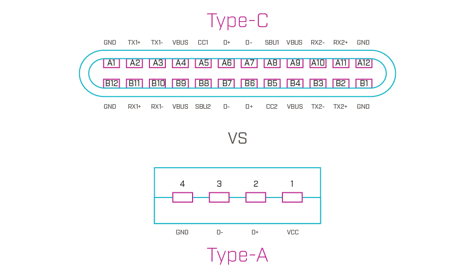
As we have mentioned, USB connectors contain varying amounts of contacts, or pins, depending on the version of the standard they support. When a USB interconnect is connected to a device, each of the pins plays a role in terms of data transfer, power delivery, ground, or device identification. Obviously, pin connections are crucial for correct communication between the host and the peripheral.
USB pinout (or pin layout) refers to the arrangement of the pins in the connector. Each pin connects to a different color of wire in the cable to keep the function consistent throughout the interconnect. The wire colors correspond to the purpose of the wire. You should look up wire color charts for the particular connector you plan to use.
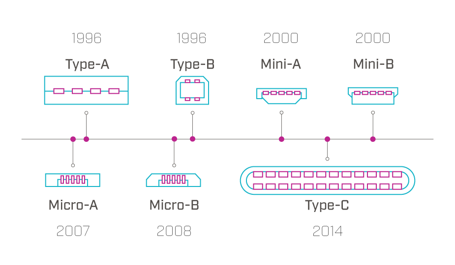
The total number of pins in a USB connector has grown over the years as the standard has changed to support more sophisticated devices. The original four-pin USB-A version has four pins: two for data, one for power, and one for ground. The USB Type-C connector has 24 pins: sixteen for data, four for power, and four for ground. This table shows the pin counts by USB connector type and how they have changed over the years.
| USB Connector Type | USB Version Supported | Number of Pins | Date Released |
|---|---|---|---|
| Type-A | USB 1.0 | 4 | 1996 |
| Type-B | USB 1.1 | 4 | 1998 |
| Type-A | USB 2.0 | 4 | 2000 |
| Type-B | USB 2.0 | 5 | 2000 |
| Mini-A | USB 2.0 | 5 | 2000 |
| Mini-B | USB 2.0 | 5 | 2000 |
| Micro-A | USB 2.0 | 5 | 2000 |
| Micro-B | USB 2.0 | 5 | 2000 |
| Type-A | USB 3.0 | 9 | 2008 |
| Micro-B | USB 3.0 | 10 | 2008 |
| Type-B | USB 3.0 | 9 | 2008 |
| Type-C | USB 3.0 | 24 | 2014 |
| Type-C | USB 3.1 | 24 | 2014 |
| Type-C | USB 3.2 | 24 | 2017 |
| Type-C | USB4 | 24 | 2019 |
| Type-C | USB4 v2 | 24 | 2022 |
USB pinout is similar to a roadmap, or diagram of how data and power flow through a device. In the pinout for a particular connector, you will see pins marked with D+ and D- for data transfer and device synchronization, VBUS for power, and GND for ground. The ID pin differentiates host from peripheral and is crucial to proper communication. USB 3.0 and later versions of the standard may also indicate SS+ and SS- pins, which are used for SuperSpeed data transfer in high bandwidth applications.
Pin functions in male connectors must match those in their female receptacles. Different pinout configurations in different USB versions allow for a variety of data transfer speeds and power levels to enable functions like faster charging, high-speed video, and more.
USB Differential Signaling Explained
The USB protocol also employs differential signaling to reduce or cancel outside electrical interference. This technique involves the sending of two complementary signals in two separate conductors. These signals are equal in voltage magnitude but opposite in polarity. Simply put, the receiver interprets the voltage difference between the two signals as the data.
While this method has been extrapolated out with the increase of pins in each connector, at its most basic, it involves two wires, D+ and D-, that have different electrical voltages, high or low. These two lines are measured at regular intervals and if they have not swapped polarities, this indicates the value of 1. If they toggle, this indicates a value of 0. To check for problems where the lines may be erroneously stuck at their current value, the practice of “bit stuffing” is used where a “0” is inserted after every six consecutive “1” bits, toggling the lines. There are more complexities to handle overhead and ever-higher signaling rates, but at its most basic, USB signaling relies on this principle of the differential lines swapping to indicate a 0 and not swapping to indicate a 1.

Key Design Considerations for USB Interconnects
Designing or selecting the right USB interconnect solution for your project should involve numerous factors. Here are several of the most important. Please note that, while extensive, this list may not be all-inclusive.
How Does Backward Compatibility Affect USB Performance?
Depending on connector configuration, USB interconnects are backwards compatible, so newer versions will work with older versions. The device, however, will only run at the speed of the port into which it is plugged.
What Are the Maximum USB Cable Lengths?
The USB standard was originally designed to connect peripherals on the same tabletop, so USB 3.0 recommends a maximum cable length of 3 meters and a maximum of 5 meters for USB 2.0. If the cable is too long, signals can deteriorate and significantly impact usability. The use of high-quality cable may affect these distances. An active or repeater cable, or a hub should be used for longer distances.
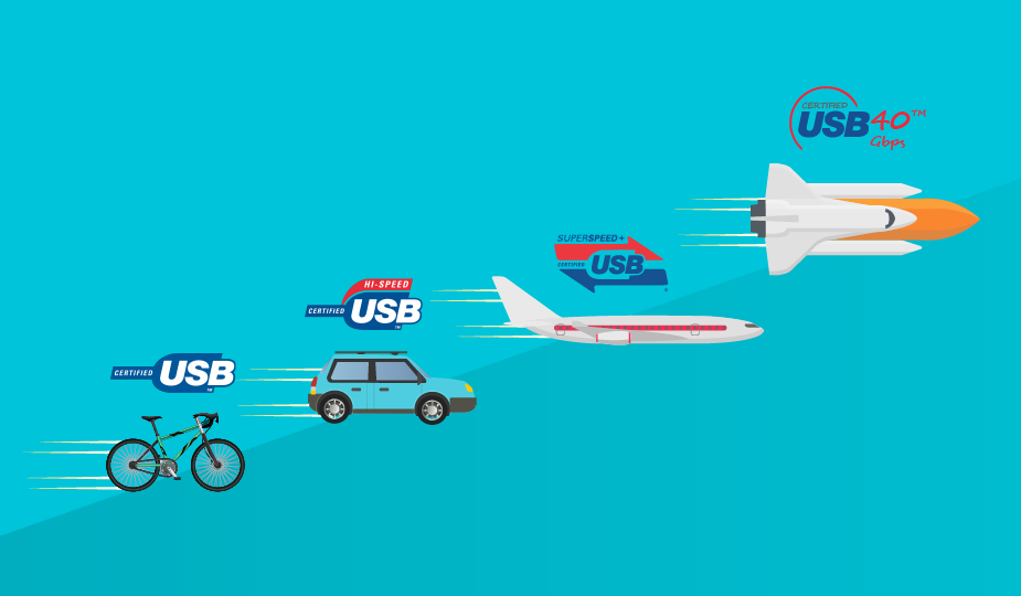
Why Is USB Certification Important?
USB interconnects can be tested to USB-IF quality standards and give a bandwidth and power rating. Using the USB logo on a device, however, is only permitted after compliance testing, to assure that a device will work as expected. If your need is for high reliability, particularly with charging cables that will see frequent use, you may want to source devices with reinforced connectors or cable.
What Causes Common USB Bus Errors?
USB-related issues can be caused by faulty cables, outdated drivers, power management issues, incompatible devices, or physical damage to the interconnect. These can usually be tracked by checking the pinout, checking for physical damage, running a hardware diagnostic, or checking device functionality. Programming issues at the development level can include data sequencing, enumeration errors, speed or power issues, or reset events. The USB interface defines protocols for recovery from common errors.
USB Communication Protocol
For product design considerations, remember that USB uses a master/slave protocol for addressing peripheral devices, meaning that peripheral devices cannot interact with each other except through the host, and two hosts cannot communicate directly over their USB ports. A host can also not broadcast signals to all connected peripherals at once.
USB Contact Materials and Plating
Depending on the manufacturer, USB contacts are available in a range of contact materials and plating to resist wear, corrosion, and provide the desired level of conductivity. Plating thickness of the contacts is a determining factor in mating cycle ratings for USB connectors.
USB Data Transfer Speed Requirements
A wide range of transfer speeds are available from the various USB interfaces to facilitate devices ranging from keyboards to video interfaces. However, a USB interconnect must be rated for the speed required to accommodate your needs. Be sure to know the data transfer needs of your device before deciding on a USB solution. Also note that USB data transfer rates are slower than some other interconnects, like 100 Gb Ethernet.
USB Mounting and Mechanical Considerations
USB interconnects can be mounted using various methods such as surface-mount technology (SMT) for compact, automated assembly, through-hole mounting for added mechanical strength in high-stress environments, or mid-mount SMT (MSMT) for reducing vertical profile in slim devices. Board edge connectors offer a convenient solution for plug-in modules or hot-swappable devices, ideal for applications requiring easy access or frequent replacement.
Are All USB Connectors Polarized?
All USB connectors are polarized, with the exception of USB-C, which is designed to be reversible (non-polarized). Polarization ensures that a connector can only be inserted into a port in the correct orientation in order to protect devices from damage.
How Does USB Power Delivery Work?
All USB versions, with the exception of USB 1.0, provide power to the connected peripheral, but at varying levels. USB power delivery ranges from 500 mA for USB 1.1; to 48 V and 5 A under the USB Power Delivery (USB PD 3.1) standard. USB PD also offers fixed voltages and power levels, adjustable voltage supply, power optimization across multiple devices, intelligent power management, and bi-directional power supply. Remember that a device can only draw as much power as the port supplies, so you will need to match the power needs of your device to the capabilities of the interconnect.
Shielding and Grounding in USB Connectors
As we mentioned earlier, all USB connectors are effectively shielded since they have a metal shell surrounding the internal conductors to protect against outside electrical noise from interfering with data transmission. This shield is typically connected to the ground on the connector. USB cables also have some level of shielding (but not always), and higher-quality cables will often have a more robust level of shielding.
All standard USB connectors are also grounded as the USB host will typically link the connector to ground through the shield. The ground pin also connects to the peripheral through a dedicated ground wire in the cable when plugged in. Grounding is obviously crucial for the proper functioning of the device and protection from damage.
Summary
USB interconnect technology is an effective, efficient, and proven solution for connection and communication between all types of modern electronic devices and systems. The numerous USB standards and the interconnect devices that support them offer a broad range of data and power delivery specifications to match the needs of designers in settings that range from the home to the factory floor. USB ports are available in various mounting options, including panel, surface-mount, through-hole, or hybrid, with placements on the top, middle, or bottom of the board, and in horizontal or vertical orientations. Today’s USB interconnect products are designed not only for functionality and interoperability but also for streamlined manufacturing and cost-effective scalability, making them an intelligent solution to your interconnect challenges.
Key Takeaways
- USB connector technology enables both data and power delivery in a single, cost-effective, and widely adopted interconnect solution.
- USB standards have evolved from USB 1.0 to USB4, increasing data transfer speeds, power capacity, and connector functionality.
- USB connector types differ in design and pin count, ranging from four-pin USB-A connectors to 24-pin USB-C connectors.
- USB communication uses a host–peripheral architecture, where the host controls data flow and power delivery.
- USB pinouts define electrical functions, including data (D+/D-), power (VBUS), ground (GND), device identification, and SuperSpeed signaling.
- Differential signaling improves USB signal integrity, reducing noise and enabling reliable high-speed data transfer.
- USB interconnect selection requires multiple design considerations, including compatibility, cable length, data speed, power delivery, mounting, and certification.
- Shielding and grounding are essential for reliable USB performance, protecting against electrical interference and equipment damage.
 Tags:
Tags:
Additional Resources