Getting Started with USB: Integrating a USB Connector into Your Product
The Universal Serial Bus (USB) digital communications standard was released in 1996 to simplify the connection of communication and power sources between computers and peripheral devices. It specifies both the form of connectors and cabling along with the structure of the data passing through them. The standard has been revised several times to address the growing need for signal speed, hardware miniaturization and to add other features.
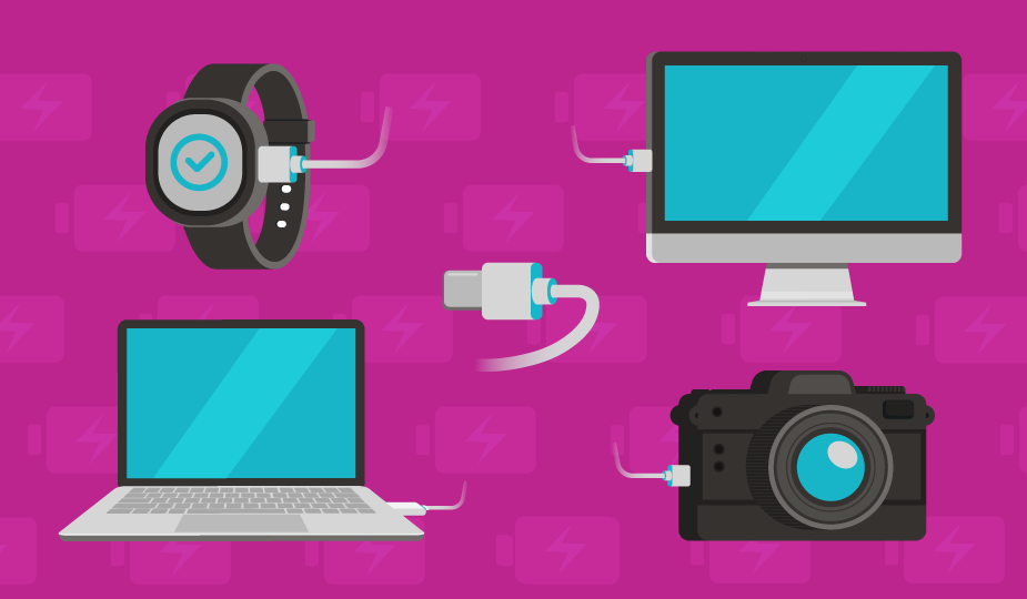
USB has seen wide adoption because of broad compatibility with many platforms and operating systems, low cost of implementation, ease of use, interchangeability, and hot-swap capability. It also enables the combination of data and power (up to 240 W) in a single connection, avoiding the need for peripheral power supplies for external devices. These attributes may make a USB interconnect solution an intelligent choice for your projects. Interested in more USB connectors content? Check out our other blog topics:
- USB Connector Technology: A Deep Dive into Architecture, Pinouts, and Signaling
- How USB Connectors Enable Modern IoT, Industrial, Medical, and More
- What You Need to Know About USB Connectors and USB Cables
- USB Type C and USB 3.2 – Clarifying the Connection
- An Introduction to Power-Only USB Type C Connectors
- USB Connector Technology: A Deep Dive into Architecture, Pinouts, and Signaling
- Or watch our USB connectors and standards video
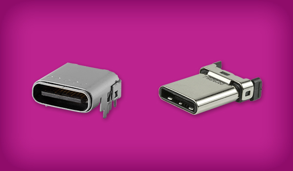
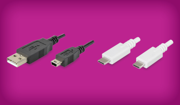
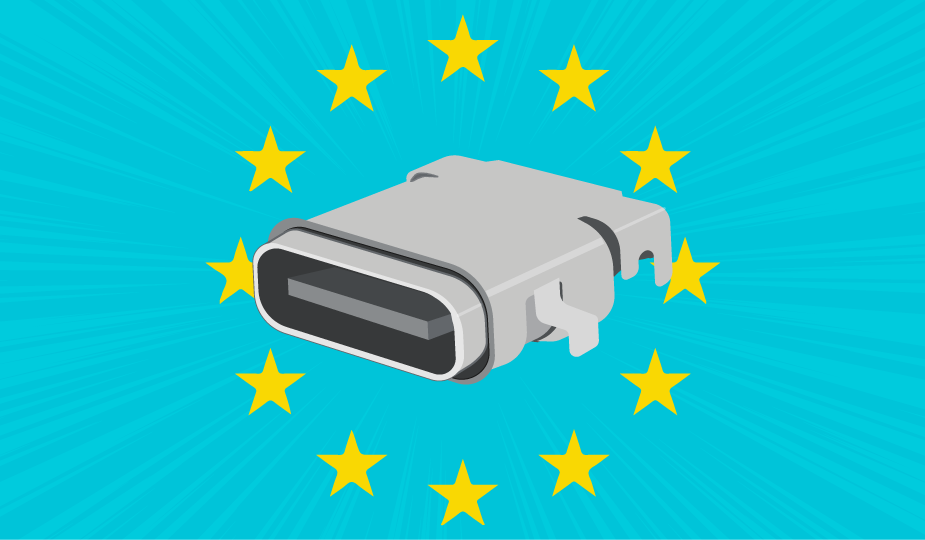
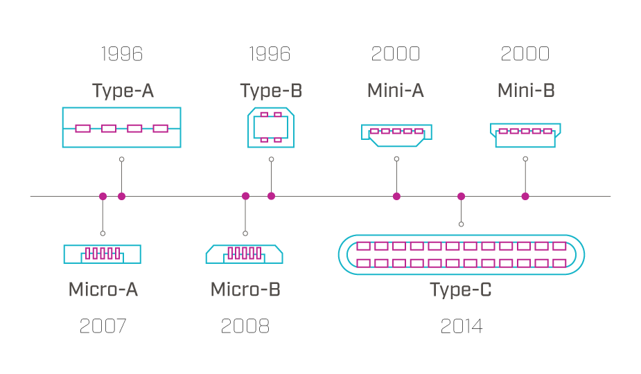
USB interconnect solutions are available in several connector configurations, including USB-A, USB-B, USB-C, Micro-USB, and Mini USB. These are all standards that describe the physical form of the connector and, important to note, are separate from the USB communication protocol standards (from USB 1.1 and USB 2.0 up to the current USB4 standard). However, USB-A is the stereotypical connector that has been utilized with computers for decades, with USB-B most popularly being used with printer connections. Micro-USB became the standard for small devices such as phones, while USB-C is becoming the de facto standard in most of the world and the official standard in the EU. For more detailed descriptions of each of these, refer to Same Sky’s blog, The History of USB Standards from 1.0 to USB4.
Understanding USB Data Transfer, Power Delivery, and Pinout Requirements
The USB protocol began as a data interface with limited power delivery that has evolved into today’s high-speed interface supplying power up to 240 W with USB PD Rev. 3.1. This integration of data and power in your design may be one of the top reasons to integrate a USB interconnect solution. The USB protocol does this by using dedicated wires within the connector and cable for data signals or power current.
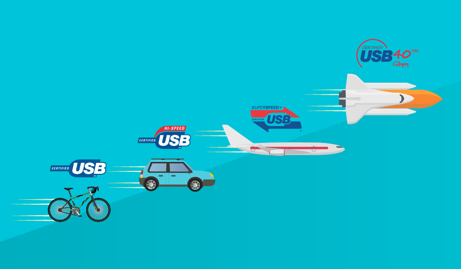
The USB protocol defines the rules for data transfer in each of the connector configurations. Data transfer speeds can range from 12 Mbps to 80 Gbps, depending on the USB type used. There are several types of USB data transfer to consider, including:
- Bulk Transfer for large data files
- Interrupt Transfer for devices requiring fast transfer, like keyboards
- Isochronous Transfer for real-time data, like video streaming
- Control Transfer for device configuration and status updates
Incorporating USB into your design also requires an understanding of the various wiring diagrams, or pinouts, used in each USB version to transmit data and power. Each USB connector version has a specific pinout diagram detailing the function of each of the pins and the wiring arrangement. Pinout configurations range from four pins in USB Type-A to twenty-four pins for USB Type-C.
For example, in the four-pin USB-A version, two pins transmit data, one supplies power, and one is an electrical ground. The USB Type-B connector has five pins: two for data, one for power, one for ground, and one for identification. Referring to the pinout diagrams for the various devices can help you select the USB type that most closely matches your design needs. Understanding pinout configuration is essential for proper device performance in your design.
The USB-PD (Power Delivery) standard further enhances the power delivery capabilities of USB, enabling faster and more efficient charging, bi-directional power delivery, and reversible hardware to make connection easier. It uses USB Type-C connectors and cables to enable power delivery of up to 240 W.
While the USB protocol began by offering data with limited power delivery, the options for increased power are now numerous. As a designer, you will need to match power demand to the proper USB version specification. A range of development tools are available from vendors to help in the USB-PD design process.
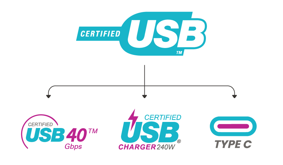
USB Compliance Testing and Troubleshooting
The widespread acceptance of USB increases the importance of quality assurance and adherence to standards through compliance testing. Adherence ensures universal device interoperability and functionality. The USB-IF (Implementers Forum) promotes and maintains USB specifications and standards. It also provides a compliance program, testing information, and certification for devices. You can access their information at www.usb.org.
Individual USB standards also provide specific information on data speeds, pinouts, and power specifications. Understanding this information is a crucial step to avoid development delays, duplicate testing, and unnecessary costs in your adoption of a USB solution for your product.
Troubleshooting USB connections begins with checking for proper pinouts. Incorrect pinouts can lead to data transfer errors, charging problems, and connection failures. It is essential to understand the metrics and testing required to verify compliance and to conduct early testing in the design stage.
Lifecycles and IP Ratings for USB Connectors
Before integrating a USB interconnect solution into your project, component lifecycle and IP (Ingress Protection) Ratings should be considered. If you’re not familiar with the IP rating system, check out Same Sky’s article, The Basics of IP Ratings. While the hot-swappable design of USB connectors is robust, all mechanical connectors suffer eventual defects from continual mating and un-mating cycles. Since USB interconnections are subject to increased use in environments ranging from the office to the factory floor, IP ratings for specific USB connector assemblies are often part of an interconnect hardware strategy.
Lifecycle ratings for USB connectors range from 1,500+ insertion/removal cycles for standard USB (USB-A) to 10,000+ cycles for USB-C and Micro-USB. Connector lifecycle is affected by its ability to maintain mating pressure, along with the quality of the contacts and plating.
Other USB Design Factors
USB interconnect solutions have been widely adopted across business, consumer, and industrial products and their popularity continues to expand. Integrating a USB solution into your product design involves issues of the data speed and/or power you require, the space you have to work with, the device durability you need, and the device orientation to match your customer needs.
It may also involve manufacturability if you are incorporating board-level interconnects in the products you manufacture. For manufacturability considerations, some newer IP-rated USB connectors (including models from Same Sky) have UV-glued O-rings that can withstand reflow soldering temperatures at the board manufacturing stage.
Given the number of manufacturers, the wide range of available devices, and the challenges of in-house production, it may be more economical for you to source an existing product than manufacture your own. Vendors also offer effective customization solutions to fit your needs.
Summary
While your product satisfies a specific need in the marketplace, its functionality, ease of use, and adaptability can help determine market acceptance. Individual components, like user-friendly, robust, and economical USB interconnect solutions can be a large positive factor in this equation.
A USB interconnect solution may be an efficient and economical path to user acceptance in the markets you target. As a designer, your task is to incorporate an understanding of the USB standards along with effective testing procedures early in your design process. Same Sky’s range of USB connectors and USB cable assemblies are here to get you started on the right path.
Key Takeaways
- USB offers universal compatibility, low cost, and combined data + power delivery, making it a strong choice for modern product designs.
- Designers can choose from multiple connector types—including USB-A, USB-B, Micro-USB, and USB-C—each with unique pinout and performance characteristics.
- USB data transfer modes and speeds vary widely, with USB4 supporting rates up to 80 Gbps.
- USB Power Delivery (USB-PD) enables up to 240 W of power, faster charging, and bi-directional power flow via USB-C.
- Correct pinout configuration is critical to prevent data errors, charging issues, and connection failures.
- USB-IF standards and compliance testing help ensure interoperability and reduce development risks.
- Connector lifecycle ratings and IP ratings should be considered for reliability, durability, and environmental protection.
- Early planning around speed, power, durability, and manufacturability leads to more successful USB integration.
 Tags:
Tags:
Additional Resources