Ultrasonic Sensors: How They Work, Key Specs, and Applications

What is an Ultrasonic Sensor?
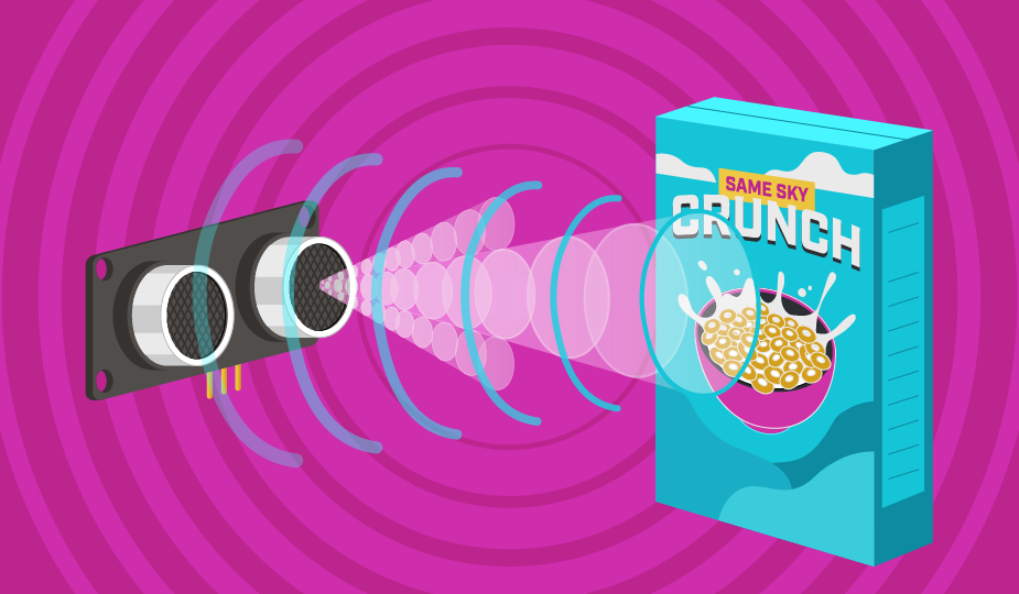
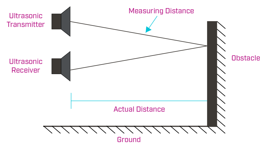
Ultrasonic sensors emit a chirp usually between 23 kHz and 40 kHz, much higher than the typical audible range of human hearing at 20 kHz, hence the term ultrasonic. Using this chirp, they measure the amount of time it takes for the sound to bounce off an object. This is based on the same basic principles of echolocation used by bats to find their prey. As the speed of sound in air at room temperature is 343 meters per second, that time can be easily converted to distance, remembering that the ultrasonic chirp travels both to and from the object being sensed.
Distance (meters) = (time elapsed [seconds] * 343 [meters/second]) / 2
The units can be changed in this equation to fit the needs of a specific application, but the simplicity of the equation shows the relatively straightforward operation of an ultrasonic sensor.
Ultrasonic sensors have been available for decades, and yet they continue to own a large portion of the sensing market due to their capabilities, flexibility, and low cost. As more products have become autonomous, demand has increased even further with their inclusion in robots, autonomous vehicles, and drones. Understanding how an ultrasonic sensor works, how it can be utilized, the pros and cons of using one, and their common applications will show how they are just as pertinent now as when they were first introduced.
How Does an Ultrasonic Sensor Work?
Ultrasonic sensing relies on both a transmitter and a receiver working together to accurately measure distance. During transmission, driver circuitry excites the ultrasonic transducer with a high-voltage pulse, causing it to generate an ultrasonic sound wave. After transmission, the receive circuitry amplifies and filters the returning echo so it can be detected and processed. Separating the transmit and receive functions helps maximize sensitivity while preventing the high-energy transmit pulse from overwhelming the much weaker returning echo. In the most standard configuration, these are placed side-by-side as close together as reasonably possible. With the receiver close to the transmitter, sound travels in a straighter line from the transmitter to the detected object and back to the receiver, yielding smaller errors in the measurements.
What are Beam Angles for Ultrasonic Sensors?
The acoustic waves that leave the transmitter are more similar in shape to light leaving a flashlight than a laser, so spread and beam angle must be considered. As the sound waves travel farther from the transmitter, the area of detection grows laterally and vertically. This changing area is why ultrasonic sensors give their coverage specification in either beam width or beam angle instead of a standard detection area. Beam angle is typically specified at the -6 dB point, representing where the acoustic energy falls to approximately half of its peak intensity. Although beam patterns are often illustrated as simple cones, the actual distribution of acoustic energy is more complex and includes a primary lobe along with smaller side lobes. These secondary lobes can occasionally produce reflections from unintended objects, making beam angle an important consideration when designing systems that operate in confined spaces or near surrounding structures. Additionally, when comparing beam angle between manufacturers, it is recommended to verify that the beam angle is either the full angle of the beam or the angle of variation from the straight line from a transducer.
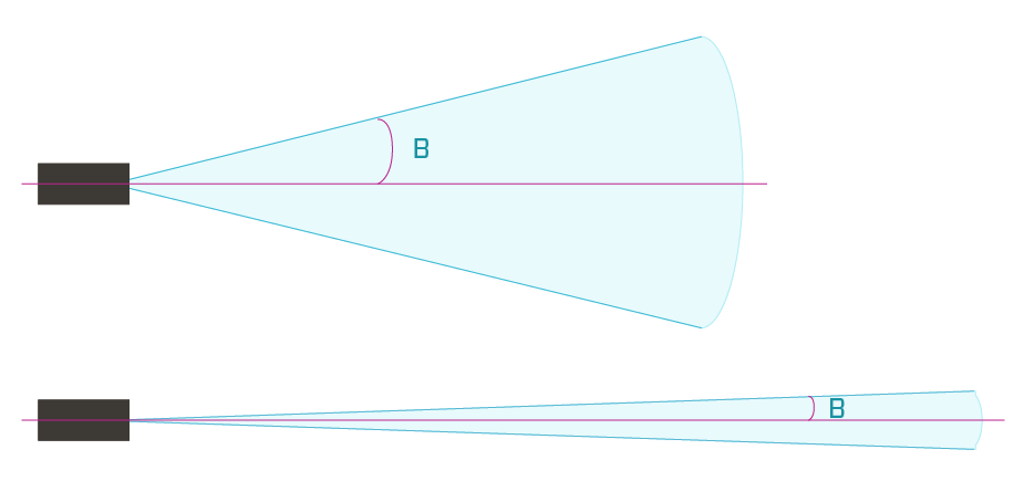
A secondary effect of the beam angle is the range of the device. In general, a narrow beam yields a greater detection range as the energy of the ultrasonic pulse is more focused and can go farther before dissipating to unusable levels. Inversely, a wider beam spreads that energy in a wider arc, reducing the expected detection range. Choosing the ideal beam width is highly dependent on the application, with wide beams better at covering larger areas and general detection, while more narrow beams avoid false positives by limiting the detection area.
Every ultrasonic sensor also has a minimum measurable distance or working range, commonly referred to as the “blind zone.” Immediately after transmitting an ultrasonic pulse, the transducer continues vibrating for a short period of time before it can reliably receive returning echoes. Objects located so close to the sensor that the reflected acoustic wave returns before the transducer stops its vibration may not be detected consistently. This blind zone is affected not only by the duration of the transmitter burst, but also by the spacing between transmitter and receiver, as well as the beam angle. While blind zones vary between sensor designs, they should always be considered when selecting a sensor for close-range measurements. Learn more about beam angles in our blog, Ultrasonic Sensor Beam Angles: How Beam Patterns Affect Detection.
What’s the Difference Between an Ultrasonic Transmitter, Receiver, and Transceiver?
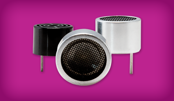
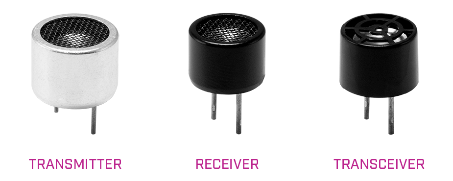
When searching for individual components, ultrasonic sensors can be acquired as independent transmitters and receivers or as a combination of the two in a single unit, known as an ultrasonic transceiver. Because ultrasonic transceivers combine the transmit and receive functions into a single unit, they ultimately save PCB space in the final design. However, transceivers typically have a larger blind zone of approximately 30 cm or more. There are higher frequency ultrasonic transceivers available that improve the blind zone down to approximately 5 cm.
The main benefit of individual transmitter and receiver combinations are their smaller blind zones in the range of 0 cm to 20 cm. They also hold better sensitivity ratings than transceivers, which has a direct correlation to detecting signals, in particular a weak signal that might be hindered by environmental factors. This is useful in power-constrained applications because the individual transmitter/receiver combo can be driven with less power than a transceiver, while still achieving the same signal sensitivity. When it comes to selecting an individual transmitter and receiver pairing, it is important to observe that their frequency ratings are within 1 kHz of each other to achieve the best signal sensitivity.
Although ultrasonic transmitters, receivers, or transceivers are often purchased separately and assembled with custom circuitry and firmware, they are also sometimes available as a single unit, pre-mounted on a PCB in the standard range finding configuration and a simple logic board. While simpler to use, designers do give up a great deal of flexibility and customization by using these modules.
Key Specifications of Ultrasonic Sensors
There are many different features and specifications to consider when choosing the ideal ultrasonic sensor for a given application. A few of them include:
- Directivity (Beam Angle): The angular spread of the ultrasonic pulse, typically specified at -6 dB. Beam angle directly influences detection range and target discrimination, or the ability to detect one target and not another. Narrow beams concentrate acoustic energy, providing greater range and improved detection of smaller objects, while wider beams cover a larger area but increase the likelihood of off-axis reflections and undesired detections.
- Range: The maximum distance over which an object can be reliably detected under specified operating conditions. Detection range depends on beam angle, operating frequency, sound pressure level, target reflectivity, and environmental conditions such as temperature and humidity.
- Function: Whether the transceiver operates with a discrete transmitter and receiver or a unified transceiver. Transmitters generate ultrasonic sound waves, receivers detect returning echoes, and transceivers combine both functions into a single package for simplified system integration.
- Output Type: Ultrasonic sensors can have either analog or digital outputs. Analog ultrasonic sensors are typically triggered by a pulse sent to the transmitter, with the receiver returning an echo signal when detected. The host controller then measures the time between the trigger and echo, decodes the signal, and calculates the distance. In comparison to an analog output, digital ultrasonic modules perform the distance calculation onboard and transmit the result to the host over a communication bus.
- Case Type: The mechanical construction and housing material of the sensor. Case designs affect durability, environmental resistance, mounting options, and acoustic performance. Plastic, aluminum, and stainless steel housings each offer different tradeoffs between cost, weight, and ruggedness.
- Enclosed Type: Indicates whether the sensor is sealed against environmental contaminants. Enclosed designs provide improved protection against dust and moisture but may require greater acoustic output to compensate for additional attenuation through the protective housing.
- Frequency: The operating frequency of the ultrasonic transducer, typically above 20 kHz. Higher frequencies generally provide narrower beam angles and better resolution but experience greater attenuation in air, reducing maximum range. Lower frequencies propagate farther but produce wider beam patterns with lower resolution.
- Sound Pressure Level (SPL): The acoustic output level (or transmitted amplitude) generated by the transmitter, typically measured in decibels (dB). Higher SPL increases the acoustic energy available for reflection, generally increasing detection range and improving performance on low-reflectivity targets. However, higher SPL also increases power consumption and can contribute to crosstalk if multiple ultrasonic sensors are being used together. Ultrasonic signals attenuate with distance due to spreading losses and air absorption, making it particularly important for long-range sensing applications.
- Sensitivity: A measure of how effectively the receiver converts returning ultrasonic energy into an electrical signal. Higher sensitivity improves detection of weak echoes from distant or poorly reflective objects but may also increase susceptibility to environmental noise and unwanted reflections.
- Voltage Rating: The maximum operating or drive voltage specified for the sensor. Maintaining operation within this rating ensures reliable performance while preventing long-term degradation or damage to the piezoelectric element.
- IP Rating: Indicates the degree of protection against dust and water ingress. Higher IP ratings allow ultrasonic sensors to operate reliably in outdoor, industrial, or washdown environments, according to their rating.
- Termination: The electrical connection method used to integrate the sensor into a design. Through-hole pins, wire leads, connectors, and surface-mount terminations each offer different advantages in manufacturing, mechanical robustness, and ease of assembly.
Strengths and Weaknesses of Ultrasonic Sensors
As with any technology, ultrasonic sensors are best utilized in certain situations or applications over others. A few of their strengths include the following:
- Ultrasonic sensors are unaffected by the color of the objects being detected, including translucent or transparent objects such as water or glass.
- Their minimum and maximum ranges are quite flexible, with most ultrasonic sensors capable of detecting as near as a few centimeters up to approximately five meters. Specifically configured modules can even measure up to nearly 20 meters.
- With decades of use, this mature technology is very reliable and well understood, yielding consistent results.
- Ultrasonic sensors provide relatively precise measurements, within 1% typically and even more precision if desired.
- They can make many measurements per second, yielding quick refresh rates.
- As there are no rare materials needed, they are usually quite inexpensive.
- Ultrasonic sensors are resistant to electrically noisy environments as well as most acoustic noise, particularly when using modules equipped with encoded chirps.
Although a versatile technology, ultrasonic sensors do have several limitations to consider before making a final sensor selection:
- As the speed of sound is dependent on temperature and humidity, environmental conditions may change the precision of the measurements.
- Although the detection zone is three dimensional, an ultrasonic sensor only detects that there is something a certain distance from the detector and cannot provide feedback on where the object is in the sensing area nor any features such as shape or color.
- While their form factor is relatively small and they can be integrated into cars or industrial applications without any concerns, ultrasonic sensors may be too large for very small, embedded projects.
- Like any sensor, they can get dirty, wet, or frozen, which will cause them to be erratic or non-functional.
- Due to their dependence on sound, which in turn depends on a medium of some sort, ultrasonic sensors do not work in a vacuum.
Where are Ultrasonic Sensors Typically Used?
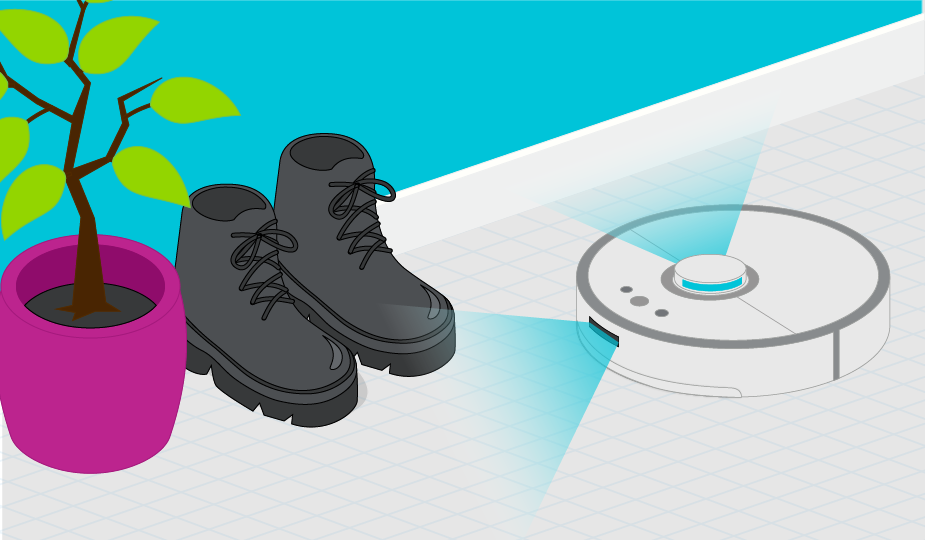
The first of the two most common ultrasonic sensor applications is liquid level sensing, as they can detect liquids of any color or opacity yet are also non-contact. The second is general object detection due to their low cost and simplicity. Specific object detection applications include anti-collision detection for vehicles, people detection, presence detection, box sorting, pallet detection with forklifts, bottle counting on drink filling machines, and many more.
An example of a more creative usage for ultrasonic sensors would be to use the one-way functionality of ultrasonic transmitters and receivers separately. While the ultrasonic pulses are outside of human audible ranges, they are within the hearing ranges of various animals. An ultrasonic transmitter could conceivably use its emitters to scare off animals, such as birds, while an ultrasonic receiver could be used for noise detection.
Summary
Ultrasonic sensors are a well-known technology that continues to be extremely relevant in many industrial and consumer applications. Their simplicity, low cost, and robust build make them an excellent choice for many new products requiring presence detection or distance measurement. Yet the ability to change both the hardware and software configurations make them extremely versatile for even more demanding situations. While understanding the basic operation and specifications of ultrasonic sensors is the first step, real-world performance is also heavily influenced by beam geometry, characteristics of the target being sensed, and environmental conditions.
Key Takeaways
- Ultrasonic sensors calculate distance by measuring the time required for a high-frequency sound pulse to travel to an object and return.
- Beam angle affects detection coverage, range, and target discrimination, while the blind zone determines the minimum distance that can be measured reliably.
- Separate transmitter and receiver pairs typically offer smaller blind zones and greater sensitivity, while transceivers reduce PCB space and simplify integration.
- Important selection criteria include range, frequency, beam angle, sensitivity, sound pressure level, output type, housing, environmental protection, and termination style.
- Temperature, humidity, target reflectivity, surrounding objects, and sensor contamination can all influence real-world measurement accuracy and reliability.
- Their low cost, flexible range, and ability to detect objects regardless of color or transparency make ultrasonic sensors well suited for level sensing, presence detection, and obstacle avoidance.
 Tags:
Tags:
Additional Resources