A Guide to Pin Headers: Male, Female, and Box Headers
What Are Pin Headers?
Pin headers are electrical connectors commonly used to make board-to-board and wire-to-board connections in electronic systems. They consist of one or more rows of conductive contacts held in an insulating housing and are available in male, female, and shrouded configurations to suit different connection needs.
Pin headers are a subset of the broader category of rectangular connectors. The first step to choosing the right pin header starts with determining how the connection will be made, then matching specifications such as the pitch, pin count, rows, and physical dimensions before verifying the electrical and environmental ratings.
What Are the Main Types of Pin Headers?
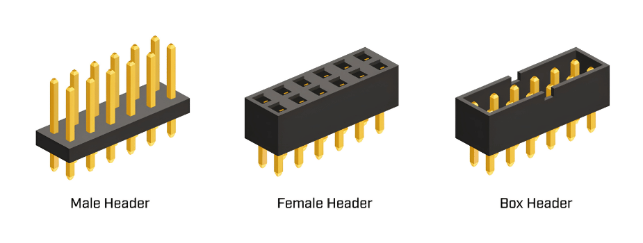
Male Pin Headers
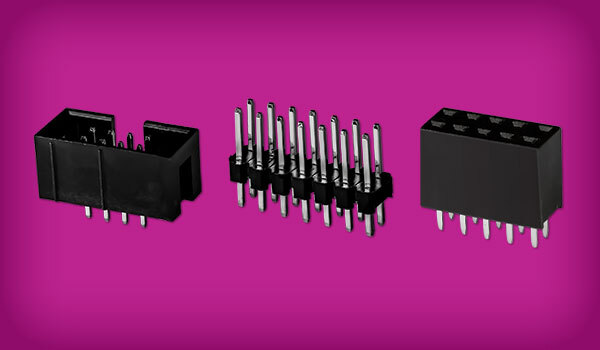
Male pin headers use exposed conductive pins that extend from an insulating housing. They mate with female receptacles to connect one PCB to another, or serve as an interface for compatible cable connectors, jumper wires, and other assemblies. Their simple construction makes male headers compact and versatile, but the exposed pins offer less physical protection than enclosed contacts.
Female Pin Headers
Female pin headers, also called socket headers or receptacles, contain contacts designed to accept corresponding male pins. They are commonly paired with male headers to create removable board-to-board connections, such as plugging a daughterboard or module into a main PCB. The housing protects the recessed contacts but also adds to the physical height of a board-to-board connection.
Box Headers
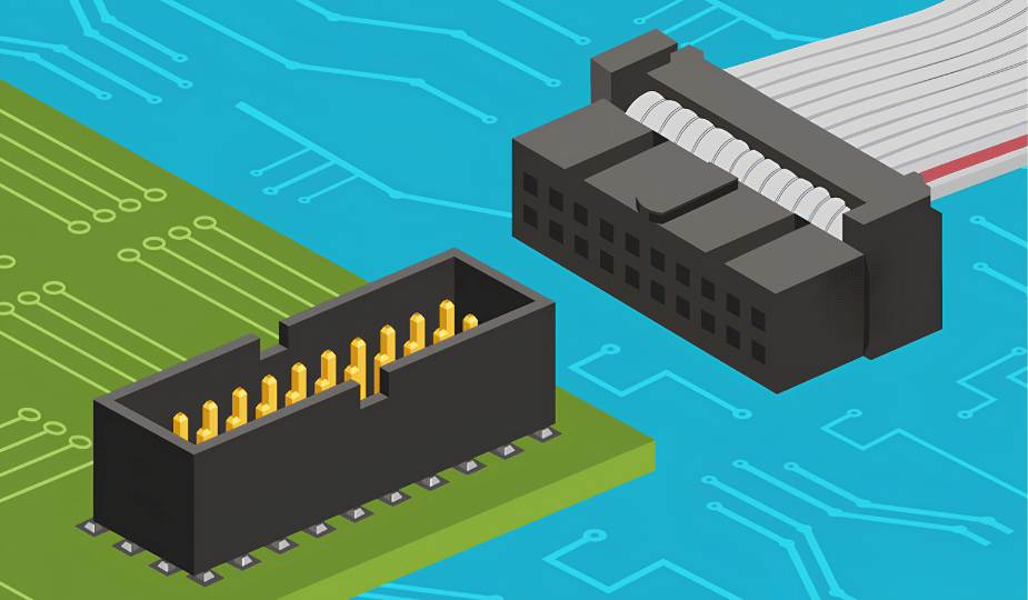
Box headers, which are sometimes called shrouded headers, are male headers surrounded by an insulating enclosure. They are commonly paired with compatible cable connectors, including IDC connectors used with ribbon cables. The shroud protects the pins from physical damage and guides the mating connector into position. Depending on the connector design and mating component, the interface can also incorporate features that help prevent incorrect insertion. Compared with an unshrouded male header, however, the enclosure requires additional PCB space and limits direct access to pins.
The table below summarizes how the three types compare.
| Male Pin Header | Female Pin Header | Box Header | |
|---|---|---|---|
| Contact Interface | Exposed male pins | Recessed female contacts | Shrouded male pins |
| Common Mating Component | Female header or cable connector | Male pin header | Compatible socket or cable connector |
| Pin/Contact Protection | Pins completely exposed | Contacts enclosed by housing | Pins protected by shroud |
How to Choose a Pin Header: Key Specifications
Pin count alone does not determine whether two connectors are compatible. Designers also need to consider the mating interface, footprint, physical dimensions, PCB mounting type, and electrical requirements.
Pitch, Rows, and Pin Count
Pitch, rows, and pin count determine whether a header mates correctly and how much board space it needs.
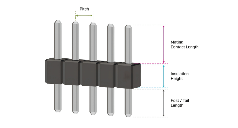
- Pitch is the center-to-center distance between adjacent contacts. The mating components and PCB footprint must use the same pitch, and multi-row connectors must also match in row spacing. The most common pitch is 2.54 mm, while 1.27 mm is also widely used. Dual-row 2.54 mm headers usually use 2.54 mm row spacing as well.
- Pin count sets the number of available connections, while the number of rows shapes the footprint. A dual-row header fits more contacts into a shorter length than a comparable single-row header. Single- or dual-row headers are the most common configurations.
Same Sky’s SSK pin headers and box headers offer 1 mm, 2 mm, and 2.54 mm pitches and are available in single- or dual-row configurations, depending on the series.
Mating Length, Post Length, and Insulation Height
Several dimensions determine how a header fits within the finished assembly.
- Mating contact length is the exposed portion of a male contact available to enter the mating connector. It must provide sufficient engagement with the female contact without interfering with the intended mechanical fit.
- Post length, also called tail length, is the portion of the contact extending from the opposite side of the insulator toward or through the PCB. On through-hole connectors, post length must suit the PCB thickness and soldering requirements. On standard headers, a 3 mm post length is typical and fits standard 1.6 mm-thick PCBs well.
- Insulation height is the height of the insulating body. It helps determine how much space the connector occupies in the assembly, which is especially important when stacking boards or working within a space-constrained enclosure.
Straight vs. Right-Angle Headers and PCB Mounting Options
Orientation and mounting styles define how a pin header is positioned relative to the PCB and how it attaches to the board.
- Orientation determines how the mating component approaches the PCB. A straight header creates a connection perpendicular to the board surface, while a right-angle header redirects the connection parallel to the board. This choice influences board stacking, enclosure layout, and cable routing.
- Mounting style must also match the PCB design and assembly process. Through-hole connectors use posts inserted through drilled PCB holes and are more common, while surface-mount connectors attach to pads on the board surface.
Electrical and Environmental Ratings
Mechanical compatibility is only part of the connector selection. Designers should also verify the following against the application needs:
- Current and voltage ratings
- Operating temperature
- Contact material and finish
- Expected mating life
- Environmental ratings
These values should be confirmed for the specific connector and not assumed from its pitch or appearance.
Where Are Pin Headers Used?
Different applications emphasize different selection criteria, and, in each case, the application determines which specifications matter most.
Board-to-Board Connections
Male and female headers are a common way to join a main PCB to a daughterboard, module, or an expansion board. Because the connection is removable, the attached board can be replaced or upgraded without desoldering. Connector height is important here because it affects the spacing between the PCBs.
Wire-to-Board Connections
Pin headers also give cables and wires a defined connection point on the PCB, linking the board to front-panel controls, displays, sensors, or other electronic assemblies. Male headers can mate with crimped cable connectors or jumper wires. A ribbon cable connection may work better with a box header and compatible IDC socket due to the way the shroud guides the connection.
Embedded and Industrial Systems
In embedded systems and industrial equipment, pin headers provide internal connections between boards and subassemblies. Programming or configuration interfaces may use an exposed male header for easy access to individual contacts. Where equipment faces temperature extremes or vibration, the connector’s ratings and how securely it stays mated deserve greater scrutiny.
Prototyping and Development Boards
Development boards, evaluation kits, and single-board computers often use pin headers to expose GPIOs for sensors, modules, and expansion boards. Jumper wires can connect directly to the headers, and female headers let modules plug in and be swapped as the design changes and improves. The common 2.54 mm pitch also matches the spacing of solderless breadboards, making them ideal for prototyping and development purposes.
Pin Headers from Same Sky
Same Sky’s rectangular connector portfolio includes male pin headers, female pin headers, and box headers across multiple series. The family offers single and dual-row options with up to 40 pins total, multiple pitch options, surface mount or through-hole mounting, gold-flash contacts, and several insulation heights. This range lets engineers and designers match the connector to the mating interface, pin count, physical dimensions, and electrical requirements of their application.
Key Takeaways
- Pin headers are a type of rectangular connector, used for board-to-board, wire-to-board, test, programming, and other internal connections.
- Male and female headers commonly form the two halves of a connection, while box headers add a shroud for greater pin protection and mating guidance.
- Pitch, row spacing, and pin count must match the PCB footprint and the mating component.
- Mating contact length, post length, and insulation height affect how the connector physically fits and mates within the assembly.
- Electrical and environmental ratings should always be verified for a specific connector, not assumed based on the size and pitch.
Frequently Asked Questions
Are pin headers rectangular connectors?
Yes. Pin headers are one type of rectangular connector. The rectangular connector category covers many connector styles with a generally rectangular shape, including pin and socket headers as well as other board and cable connector systems.
What is the standard pin header pitch?
The most common header pitch is 2.54 mm (or 0.1 inch), although other pitches are available. Pitch is the center-to-center spacing between adjacent contacts, and both sides of a mating connection must use the same pitch.
What is the difference between male and female pin headers?
Male pin headers use exposed pins, while female headers contain recessed contacts designed to accept those pins. The two are frequently used together to create removable board-to-board connections.
What is the difference between a pin header and a box header?
An unshrouded male pin header leaves its pins exposed, while a box header surrounds them with a protective shroud. The shroud adds pin protection and mating guidance, making box headers useful for applications such as ribbon cable connections.
What is the difference between mating contact length and post length?
Mating contact length is the portion of a male contact that engages the mating connector. Post length, or tail length, is the portion extending from the other side of the insulator toward or through the PCB. Mating length affects connector engagement, while post length affects PCB mounting.
 Tags:
Additional Resources