How to Increase the Audio Output of a Piezoelectric Transducer Buzzer
How Do I Maximize the Sound of a Piezo Transducer Buzzer?
In most applications the reason for utilizing a piezoelectric transducer buzzer is to create a loud sound. The amplitude of the sound produced by a buzzer is ultimately dependent upon both the specific buzzer selected and the signal used to drive the buzzer. There are several ways to affect the audio output of a piezo buzzer based upon the design of the driver circuit. This blog outlines the working principles of piezo transducers, common design techniques for increasing audio output, and the advantages and limitations of each. Shop Same Sky's full range of buzzers here.
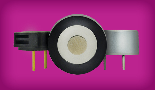
How Piezoelectric Transducer Buzzers Work
A piezoelectric transducer buzzer generates sound by converting electrical energy into mechanical vibration. When a voltage is applied, the piezoelectric material deforms, producing sound waves. The magnitude of this deformation, and resulting sound pressure level (SPL), scales with the applied voltage
Unlike indicator buzzers, which contain an internal oscillator and operate from a DC supply, transducer buzzers require an external excitation signal. This allows precise control over frequency, tone, and output, making them well-suited for applications requiring customizable audio feedback. The basics of piezoelectric transducer buzzers are described in greater detail in our Buzzer Basics blog post as well as our Buzzer Basics video.
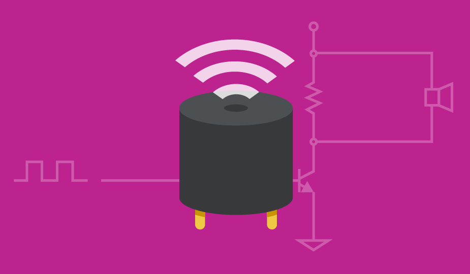
Basic Piezo Transducer Drive Circuit
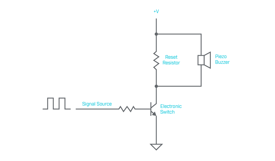
One of the most basic piezo transducer drive circuits is composed of an electronic switch, such as an FET or BJT, and a reset resistor as shown in the circuit below. The main advantage of this circuit is it only requires a few, inexpensive parts. The primary limitation of this approach is that the voltage applied to the buzzer is effectively capped at the supply voltage (+V), and in practice may be somewhat lower due to voltage drop across the switch. Additionally, the reset resistor dissipates power, reducing overall efficiency. It should be noted that the buzzer and circuit behave the same regardless of whether the one buzzer terminal is connected to the +V supply (as shown in the schematic) or to ground.
Understanding Piezo Transducer Voltage Ratings
Piezo transducer voltage ratings are often given in Vp-p, which applies to a bipolar AC drive signal rather than monopolar DC operation. Since Vp-p describes the full peak-to-peak voltage swing, the equivalent Vo-p value is half of that amount. For instance, a transducer rated at 30 Vp-p has an equivalent limit of 15 Vo-p. Exceeding that Vo-p level means the device is being driven beyond its rated operating voltage.
Adding Buffers to a Piezo Transducer Drive Circuit
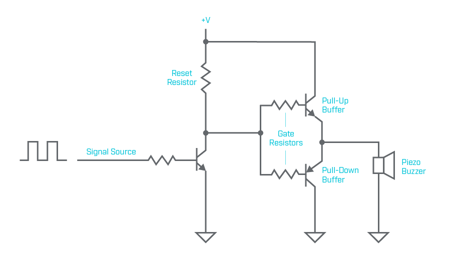
Adding two buffer transistors, as shown in the circuit below, can reduce power loss in the piezo transducer drive circuit detailed previously by allowing a higher-value reset resistor to be used. A drawback of this circuit is that the two buffer transistors reduce the voltage applied to the buzzer by about two diode drops, or roughly 1.2 Volts. As with the basic driver circuit, the buzzer and circuit behave the same regardless of whether one buzzer terminal is connected to the +V supply or to ground.
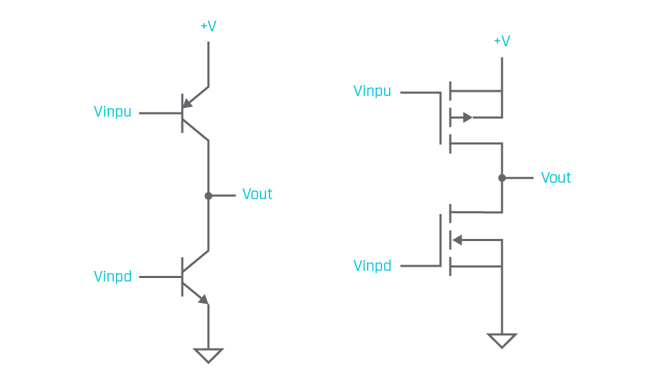
The reduced voltage applied to the buzzer can be addressed by reversing the positions of the BJT buffers in the initial buffered driver. This circuit can also be constructed with FETs instead of BJTs as the buffer components. Both buffer configurations are shown below.
Half-Bridge vs. Full-Bridge Piezo Transducer Drive Circuits
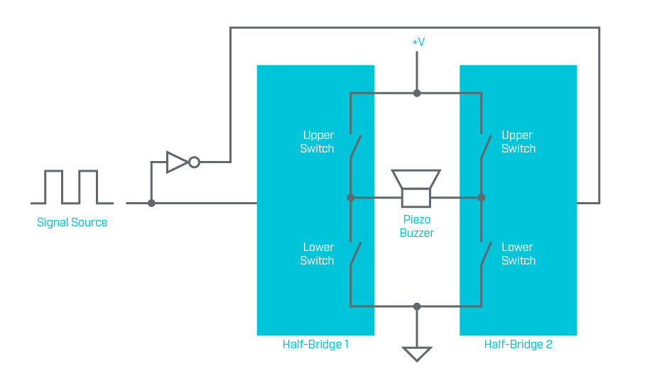
The changes to the buffer configuration mentioned in the previous section will require the drive circuit for the buffers to be more complex, which may not be desired when implementing a solution with discrete components. Doing so requires complementary control of the two push-pull buffer stages. This type of driver with push-pull buffers is commonly referred to as a “half-bridge” driver.
A full-bridge driver consists of two half-bridge drivers driven out of phase, with the piezoelectric transducer buzzer connected between their outputs. The advantage of using a full-bridge driver is that the voltage applied across the buzzer can approach twice that of a basic driver or half-bridge driver. However, the actual voltage will be somewhat lower due to voltage drop across the transistors. This increased drive voltage results in a louder output sound from the buzzer while using the same supply voltage. Many versions of both half-bridge and full-bridge drivers are available as inexpensive integrated circuits and are often used to drive electric motors.
Resonant Piezo Transducer Drive Circuit
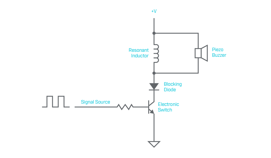
Yet another option for driving a piezo transducer is to create a circuit that utilizes the capacitance present in the transducer buzzer and a discrete inductor to form a resonant circuit. One characteristic of a resonant circuit is that energy is stored and transferred alternately between two elements. In this application, the two elements that store and transfer the energy are the inductor and the capacitor. The schematic drawn below is one possible implementation of a resonant piezo transducer drive circuit. Some advantages of a resonant drive circuit are:
- Simple to construct
- High electrical efficiency
- Voltage developed across the piezo buzzer can be many times larger than the supply voltage
However, the operation of the circuit is dependent upon the capacitance of the piezo transducer, which may not be well characterized or controlled during the manufacturing process. Depending upon the desired operating frequency, the inductor could be physically large and heavy relative to the other circuit components. It can also be difficult to model the operation of the resonant circuit and thus the circuit may need to be finalized in the lab rather than at the design computer. An additional limitation is that the resonant piezo transducer drive circuit only performs well over a narrow frequency range, making it less suitable for applications where multiple frequency tones are required.
A more detailed discussion and analysis of the resonant driver circuit can be found in this article by EDN. It should be recognized that the circuit in the referenced article is for operation at 40 kHz. Therefore, you will need to scale the component values for operation at an audio frequency of perhaps 4 kHz.
Summary
The designer has choices and trade-offs to make regarding the selection and design of a driver for a piezoelectric transducer buzzer. Many of the trade-offs involve the cost of designing and manufacturing the drive circuit. However, once a power supply voltage has been determined, the transducer driver may be limited in the ability to enhance the output sound volume. If output sound volume is proving to be a challenge, an appropriate sound volume may be achieved by incorporating the proper drive circuit in conjunction with a buzzer with an optimal voltage rating, size, and mounting style. Same Sky’s diverse offering of buzzers simplifies this selection process with a large range of configurations to match the specific requirements of your application.
Key Takeaways
- Sound output (SPL) is primarily driven by voltage. Higher voltage across the piezoelectric material produces greater mechanical deformation and louder sound
- Drive circuit design is the most important factor in performance. Transducer buzzers rely on external excitation, so circuit topology directly impacts output
- Basic driver circuits are simple and low cost, but voltage is limited to the supply and power is lost in components like reset resistors
- Buffered, half-bridge, and full-bridge drivers increase the effective voltage across the piezo. Full-bridge designs can nearly double the voltage swing
- Resonant drive circuits can significantly boost output by leveraging the piezo’s capacitance and an inductor to increase voltage beyond the supply
- Operating at or near the resonant frequency maximizes efficiency and sound pressure level
- Higher output designs introduce tradeoffs in complexity, cost, and tuning requirements
- Application requirements ultimately determine the best approach, with simpler circuits suited for basic alerts and more advanced topologies used for higher output needs
 Tags:
Tags:
Additional Resources