Understanding Thermoelectric Generators: How TEG Modules Convert Heat to Power
What is Thermoelectric Generation?
In Physics 101, we are reminded that energy cannot be created or destroyed, but it can be changed into different forms. Ever since the formulation of The Law of Conservation of Energy, also known as the First Law of Thermodynamics, engineers have been trying to find ways to change energy into forms that we can more easily use.
One of those ways is thermoelectric generation, or the conversion of heat energy into electrical energy. First discovered by Thomas Seebeck, the direct conversion of heat into electricity, known as the Seebeck Effect, sees modern practical application in a solid-state device known as a thermoelectric generator (TEG). However, TEG device technology did not really begin to advance until the 20th century with the first commercial applications introduced in 1960. Now, TEGs are used in a wide variety of applications.
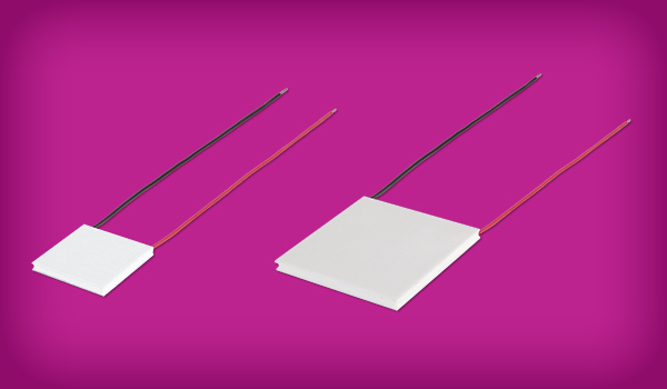
What are Thermoelectric Generator (TEG) Modules?
Thermoelectric generator modules, TEG modules, or TEGs for short, rely on the thermoelectric effect, which is the conversion of temperature differences in a material into electric voltage or vice versa. The thermoelectric effect encompasses three related aspects: the previously mentioned Seebeck Effect, where electricity is generated from the temperature gradient between two dissimilar materials; the Peltier Effect, where heat is created or absorbed at the junction of two dissimilar metals when a current is applied; and the Thomson Effect, where heat is absorbed or produced based on the direction of the current.
What is the Difference Between Thermoelectric Generators and Thermoelectric Coolers?
One common point of confusion in thermoelectric technology is the difference between a thermoelectric generator (TEG), which utilizes the Seebeck Effect, and a Thermoelectric Cooler (TEC), which uses the Peltier Effect. These thermoelectric effects are employed in different devices in different ways for current generation and solid-state cooling. The various thermoelectric devices each use different designs but employ similar materials (doped semiconductors) in their construction. While the materials are similar, TEGs are engineered for high-temperature differentials and energy efficiency, focusing on maximizing power output. TECs, conversely, are designed to optimize heat absorption and dissipation, often using advanced ceramics and copper to make the cooling more efficient. To understand more about Peltier modules, check out our in-depth blog, How to select a Peltier Module.
Although the processes are similar, if your goal is to generate power from heat, a TEG module is the best choice. If you are looking for active cooling or temperature stabilization, a TEC module or Peltier module is what you need. Luckily, Same Sky offers both TEG modules and Peltier modules, depending on your design requirements.
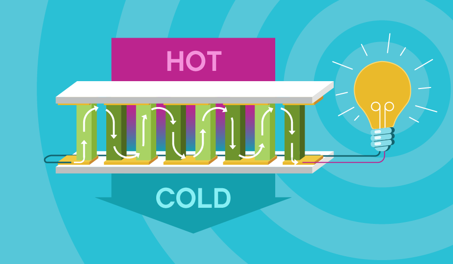
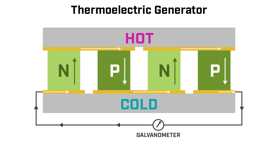
How Does a Thermoelectric Generator Work?
In a modern thermoelectric generator, the temperature difference between the hot and cold sides of a semiconductor material causes charge carriers (electrons) to move from the hot side to the cold side. Internal to the TEG module, there are multiple pairs of n-type and p-type semiconductor materials (typically bismuth telluride). These pairs of semiconductor materials are sandwiched between the hot plate and the cold plate. In an n-type material, electrons move from the hot side to the cold side. In a p-type material, holes (or the lack of electrons) also move from the hot side to the cold side. This flow results in the creation of an electrical potential (voltage) that can be harnessed as useful electric current. The voltage is proportional to the temperature difference between the two sides of the material.
TEGs are typically used in applications where waste heat is present, like industrial processes, to recover energy that would otherwise be lost. They are also used in remote applications, like space probes, to generate electricity from the heat of radioactive decay when solar energy is too weak.
Advantages of Using TEG Modules for Power Generation
From a functional standpoint, the most useful feature of TEG modules is that they take advantage of wasted heat energy to generate electrical power. This can be beneficial in many situations to reclaim or repurpose energy, making TEGs environmentally friendly.
TEG modules are also solid-state devices with no moving parts, so they are reliable, quiet, and maintenance-free. Their compact size also allows them to fit in tight space designs. Available in a wide range of voltages and currents, TEGs can reliably provide electrical power without connection to a standard power source, making them perfect for remote applications or as replacements for battery-powered systems.
Challenges of Using TEG Modules
While TEGs are robust devices that offer usable electrical current, they are not without design challenges in a project. They are dependent on ambient temperature gradients to function properly at required power outputs, making them useful only in very specific applications. TEGs also have relatively low energy conversion efficiency scores when compared to other power generation methods, averaging around 10%.
Important TEG Specifications and Performance Graphs
Designing TEG modules into a system requires attention to some key device specifications that affect performance. While the temperature difference between the hot and cold sides, often referred to as delta T, is fundamental to how TEGs generate power, it is not typically a listed specification on datasheets. Instead, manufacturers often specify Tmax, which indicates the maximum allowable temperature for safe operation, but not necessarily the optimal operating conditions.
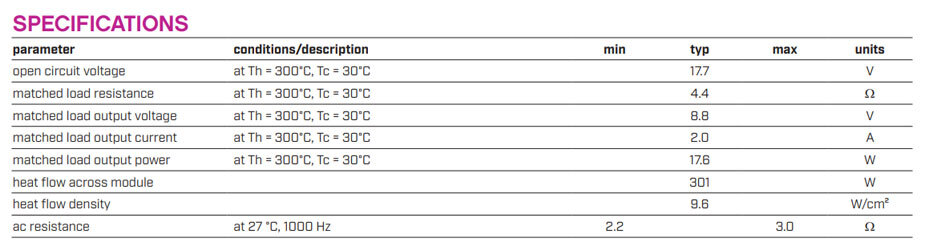
Additional useful specifications for evaluating a thermoelectric generator’s performance include open-circuit voltage, matched-load output voltage, matched-load current, matched-load power, and matched-load resistance. These values give a clearer picture of what to expect when integrating TEGs into a system with appropriate electrical and thermal loads. We go into more detail on these parameters below as we describe how they are commonly graphed in datasheets.
TEG module performance graphs represent the metrics of a TEG plotted against variables comparing the temperature of the hot side, the temperature of the cold side, and various electrical parameters. These graphs enable a designer to identify the optimal operating points or areas requiring improvement in the design. TEG performance graphs are typically used for design optimization when matching a TEG device to an application, comparing different TEG devices, or troubleshooting the final TEG system design being built. Some of the most important performance graphs are the following, recalling that “Th” represents the hot-side temperature:
- Open Circuit Voltage vs. Th:This graph represents the unloaded voltage you would see from the TEG module at a specific temperature delta. Essentially, the maximum voltage produced by a TEG. When there is a load on the TEG module, the voltage drops.
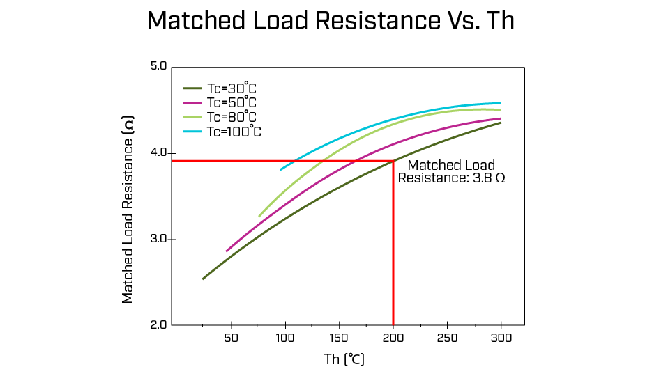
- Matched Load Resistance vs. Th: This graph shows what the internal TEG module resistance is at a specific temperature delta.
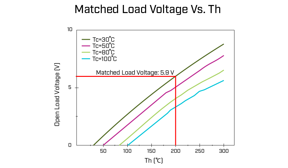
- Matched Load Voltage vs. Th: This graph shows the loaded output voltage of a TEG at a specific temperature delta.
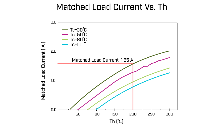
- Matched Load Current vs. Th: Similar to the matched load voltage, this shows the loaded current supplied by the TEG at a specific temperature delta.
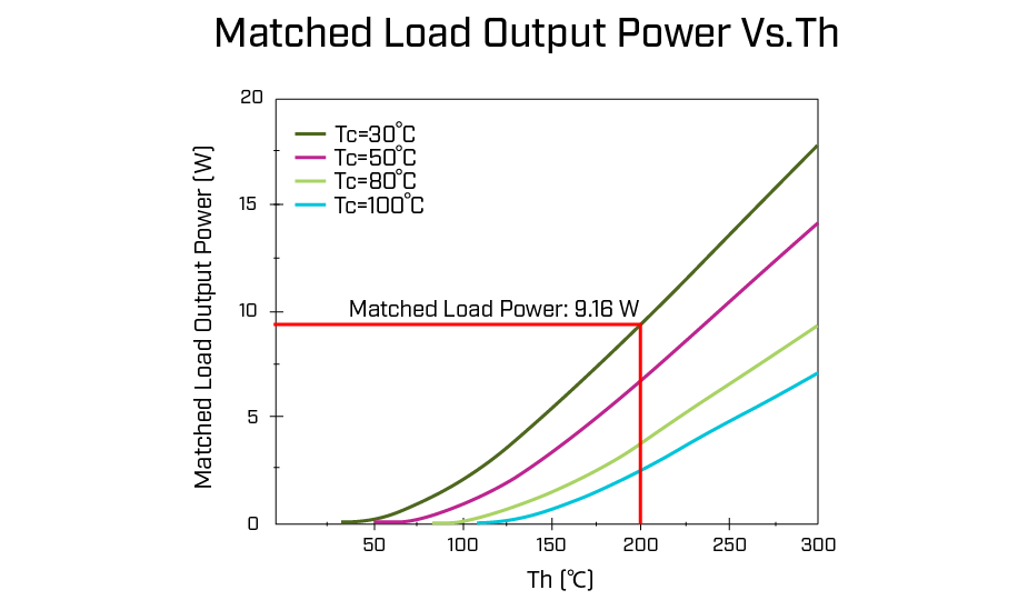
- Matched Load Output Power vs. Th: Similar to load voltage and load current but showing output power. Using Ohm's Law, you can always calculate what is shown in this graph (and vice versa). Essentially, of these three graphs, once you know two, you can always calculate the third.

The point on a performance graph where the TEG produces the highest power output, or peak power, usually corresponds to the optimal load resistance. The efficiency curve on a graph shows how conversion efficiency can change with temperature difference and load resistance. On any particular performance graph, the X-axis shows the hot side temperature of the TEG with several performance curves plotted to indicate the TEG’s cold side temperature. The Y-axis shows the particular metric being analyzed.
How to Select a Thermoelectric Generator for Your Application
To select the appropriate thermoelectric generator, the designer should start by determining the cold side and hot side temperatures to which the TEG will be exposed. Once these temperatures are determined, the designer can use the matched load voltage, matched load current, and matched load power charts from the datasheet to determine the output of the TEG in the application.
Example:
Using Same Sky’s SPG176-56 thermoelectric generator module, whose performance graphs are shown below, a cold side (Tc) temperature of 30°C and hot side (Th) temperature of 200°C, we can calculate the expected output of the TEG.
Step 1: Using the matched load voltage graph, find the Th=200°C point on the x-axis (Th) and draw a vertical line up from that point. Note where that line intersects the Tc=30°C curve. From this intersection point, draw a horizontal line over to the y-axis (V). Where this intersects is the expected output voltage from the TEG. In this example, this intersects at the 5.9 V mark, so we can expect 5.9 V from the TEG.
Step 2: Following this same process on the matched load current graph, we see the output current from the TEG will be 1.553 A.
Step 3: Using Ohm's law, the output power of the TEG is 9.16 W. This can also be verified using the matched load power chart and the same process as before.
Step 4: Using the matched load resistance chart from the datasheet and the details from our example above, we can determine that the resistance of the TEG under these conditions is approximately 3.8 ohms. TEGs follow Ohm’s Law, meaning the relationships are linear, so any combination of the graphs and use of the power formula can get the designer to the end result of the expected output from the TEG.
This nominal selection is quite straightforward; however, the real challenge is when the temperature differential is non-ideal, or the load impedance is not an exact match. At these times, the designer can refer to the performance graphs to determine the real-life performance and operating boundaries. One final note, the performance curves plot a limited number of Tc values; it is acceptable to interpolate for Tc values that are between the curves plotted.
Where Can Thermoelectric Generators be Used?
Thermoelectric generators are used in many applications where remote power is needed, or energy reclamation can add to the efficiency of a system. They are available in two versions: large and micro. Large TEGs provide output power from several to hundreds of watts and are used for industrial purposes. Micro TEGs provide from watts to a few milliwatts. Some of the current applications that use TEGs include:
- Consumer low-power devices (wearable technologies)
- Space probes and Aerospace
- Industrial waste heat recovery
- Solar energy generation
- Sensors (Internet of Things technology)
- Automotive engines
- Industrial electronic devices
- HVAC systems
- Medical health monitoring and tracking
- Military systems
- Scientific devices
- Telecom
Summary
Thermoelectric generator modules take advantage of the thermoelectric effect to generate usable electric current from temperature gradients within a device. Like thermoelectric coolers, they can be effective and efficient when closely matched to a particular application. Available in a wide variety of outputs and efficiencies, TEGs can add value to a design by enabling portability, remote operation, or energy recovery. For part selection, check out Same Sky’s thermoelectric generator modules product line featuring a range of sizes and output power ratings.
Key Takeaways
- Thermoelectric generation converts heat into electricity using the Seebeck Effect.
- TEG modules are solid-state devices that generate power from temperature differences with no moving parts.
- TEGs (thermoelectric generators) generate power using the Seebeck Effect, while TECs (thermoelectric coolers) provide cooling via the Peltier effect.
- TEGs reclaim waste heat, are quiet and reliable, and require no maintenance, making them ideal for remote or off-grid applications.
- TEGs need strong temperature gradients and have ~10% energy conversion efficiency.
- Key TEG specs include Tmax, matched-load voltage, current, power, and resistance.
- Performance graphs help match TEGs to specific operating conditions.
- Common applications for thermoelectric generators include wearables, aerospace, industrial heat recovery, IoT sensors, medical devices, and automotive systems.

 Tags:
Tags:
Additional Resources