PCB Pin Connectors: Understanding Terminal Pins, Header Pins, and More
What are Printed Circuit Board (PCB) Pins?
PCB pins are tiny building blocks of many modern electrical interconnection systems between components and circuit board assemblies. They were developed to allow connector pins to be mounted directly to a circuit board and allow interconnection without dedicated standard connectors using wire, cable, or unreliable soldered wires. Individually, they are small metal pins that can be mounted in an array to allow economical, functional, and custom connection of components to a board, or from one board to another. Their increased use in products has been driven by the unending designs of smaller and smaller electronic computing, control, and communications devices. Today, PCB pins are available in many sizes, shapes, materials, and configurations.
How are PCB Pins Used?
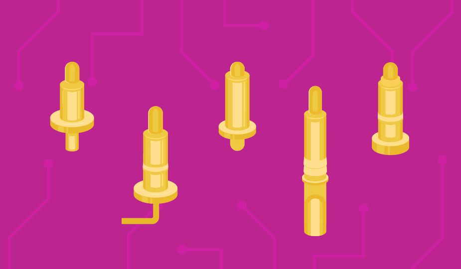
At their most basic, PCB pins are metal, tube-shaped, male connectors that are mounted, either individually, or in groups, typically directly onto a circuit board using through hole technology. They may also be employed as a part of an array with a plastic housing called a pin header.
As connectors, PCB pins require the use of a receptacle, or socket, into which the pin is inserted to make a connection. The mating of pins to headers forms a solid connection which performs electrically and mechanically to connect the function of one component or PCB to another in a system. This also allows for several design considerations, including straight and right-angle connections.
What Are the Benefits of Using PCB Pins in a Design?
Components in electronic systems can be connected in many ways, some more elegant than others. For modern designs that require interconnects that are both signal-effective and manufacturing friendly, PCB pins are hard to beat. Here are some of the benefits they can offer in your product design:
- Enable a simple conductive path for an electrical circuit
- Allow for multiple connections
- Easily adapted to suit various board configurations
- Along with a mating socket, they can also add mechanical reinforcement to a PCB
- Extensive variety allows customization across a wide variety of applications
- Offer a reliable, stable, and secure connection with no signal loss
- Durable design allows for resistance to shock, vibration, and temperature swings
- Low maintenance and easy replacement for repair or upgrade
- Cost effective compared to other connection solutions
- Low insertion force makes them easy to insert or remove
- Take up minimal real estate on the PCB enabling high-density interconnects
- Capable of high-speed data transmission as well as power or audio signals
It is probably best to stop here, as this list could get a bit long. Suffice to say that, depending on your needs, using PCB pin technology in your design may offer multiple features that can effectively add to the performance of your product or system.
What Are the Common Types of PCB Pins?
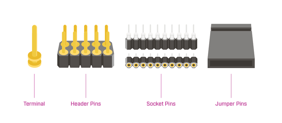
Growth in the use of PCB pin technology has meant the development of various types and styles. The basic types of PCB pins are:
- Terminal Pins: another name for individual PCB pins
- Header Pins: male connectors with individual pins that are enclosed in a plastic base
- Socket Pins: receptacle pins into which PCB pins are inserted
- Jumper Pins: small connectors used to bridge connections on a circuit board to help with testing, debugging, or design changes
What Are the Common Styles of PCB Pins?
There are also numerous PCB pin styles that accommodate various applications and/or manufacturing processes. These individual pin styles include:
- Single or Double-Ended: can connect on one end or both ends of the pin
- Single or Dual Row: one row of pins or two
- Edge Mount: mounts on the edge of and are parallel to a circuit board
- Nail Head: pin topped with a flat-faced head, like a nail
- Solder Cup: hollow pin with a concave, scallop-shaped cutout at one end to securely hold a wire and facilitate solder flow
- Slotted: pin with a vertical slot cut into it to allow easier wire insertion and soldering
- Turret: pin with one or more raised circular areas (shoulders) that allow for easier wire wrap or solder connection, or for use as test points
- Wire Crimp & Wrap: square shaped pin that enables wire to be wrapped and soldered to it
- Wire Termination: hollow pin that accepts specific wire sizes and does not allow for soldering (also known as a crimp terminals)
- Shrouded: pin with a shroud, or raised area of the body of the connector that protects the pin during assembly, insertion, and removal
- Pogo and Magnetic Pogo: spring-loaded pin with an internal compressible connection contact that can also be magnetized. Read our Pogo Pins blog for more information.
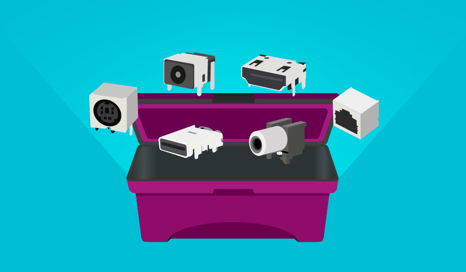
Using PCB Pins vs. Standard Connectors
When it comes to board-level design in modern electronic systems, space is everything. The unwritten law of product performance is that over time device functionality should increase while the footprint grows ever smaller.
Standard electronic connectors, while excellent for specific applications, are not usually competitive with the space-saving ability of a pin-driven connector specifically designed to adapt to the available real estate on a densely populated board. Circular connectors are relatively limited in the number of contacts they carry. Standard D-sub connectors can go up to about 50 contacts, while high-density versions offer a somewhat greater density. However, when you consider that integrated circuit devices can have 100 plus pins, you begin to see the problem.
Standard connectors, once mounted on the circuit board, can also be difficult to replace or swap-out in new designs without developing a whole new board. PCB pins can be easily grouped in large arrays by modern assembly equipment, and they remain stable and secure through multiple mating cycles, making them an ideal solution for interconnection challenges.
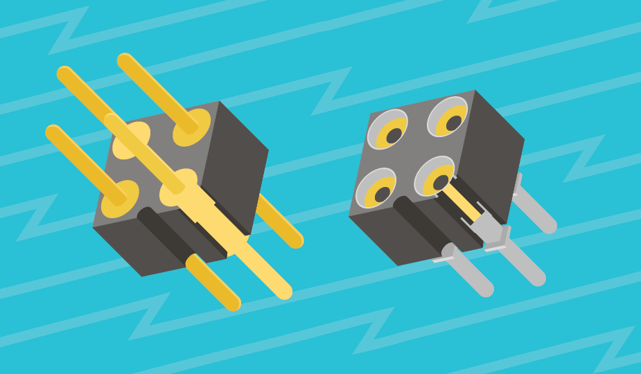
How Are PCB Pins Mounted?
PCB pins can be incorporated into a design in several different ways. The basic techniques used to attach them to a circuit board are press fit, swaged, crimped, or soldered. Each of these techniques provides various strengths of pin connection to the board dependent on the application needs. PCB pins also come in the standard mounting styles, including:
- Surface Mount: soldered to the top of the board
- Through Hole: inserted through the board and soldered in place
- Wire Mount: used to replace bare wire connections using a set screw or clamp
- Free Hanging: used to connect wire or cable together
How to Specify PCB Pins for Your Design
As with all electronic components, you will need to settle on the specifications and performance you require for your design. With PCB pins, these details include:
- Physical: Lead size, pin diameter, pin orientation (vertical, horizontal, or right-angle), mounting hole size, board thickness, pin format (round, square, or rectangular), current & voltage ratings, dimensional accuracy, and pin density
- Contact Material: typically brass, bronze, copper, or nickel
- Plating: copper, gold, silver, tin, nickel, palladium, or lead
- Manufacturing Process: how you will be inserting and attaching pins to your boards
You may also have other requirements, like harsh environment or corrosive operation, that may necessitate additional connector features.
What Are Common PCB Pin Applications?
PCB pin technology is used in a broad range of industries and applications, including computers, medical devices, test equipment, telecommunications gear, consumer electronic devices, automotive electronics, industrial automation systems, aerospace, and defense.
If you have a need for a cost-effective, efficient, and adaptable interconnect solution for your product design, PCB pin technology may be the answer you are searching for.
Summary
PCB pin connectors are a proven interconnect technology that adapts well to the needs of many and varied applications. They provide efficient and secure connections that are space-saving, simple to test, and easy to repair. Their extensive fabrication usage across electronic products in many industries, along with their role in prototyping and board development, can be an elegant answer to your interconnect needs.
Key Takeaways
- PCB pins are essential components that provide mechanical and electrical connections between printed circuit boards and other devices.
- There are various types of PCB pins, including straight pins, right-angle pins, and stackable headers, each suited for different design requirements.
- Material selection and plating options (such as gold or tin) impact conductivity, durability, and corrosion resistance.
- Pitch size and mounting style (through hole vs. surface mount) are critical factors in selecting the appropriate PCB pin for your application.
- PCB pins are widely used in applications ranging from consumer electronics to industrial control systems, facilitating signal or power transmission.
- Choosing the right PCB pin ensures reliable electrical contact, mechanical stability, and ease of assembly or repair.
 Tags:
Tags:
Additional Resources